


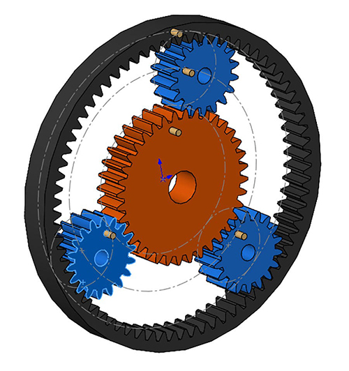
Planetary gearing is a compact various to plain pinion-and-gear reducers and is utilized in all kinds of functions to offer excessive torque. We’re going to go over the setup of a planetary gear meeting in SOLIDWORKS that can enable us to reveal the movement of the three drive forms of this method.
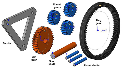
To arrange our planetary gear system, first we’ll insert the entire obligatory elements into a brand new meeting doc:
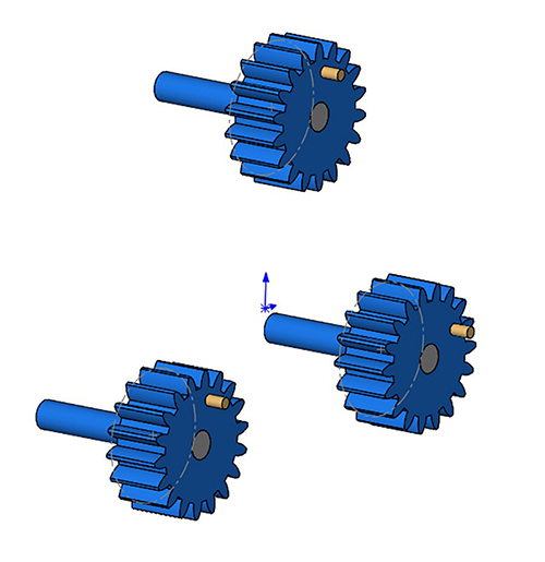
- 3 x planet gears (blue)
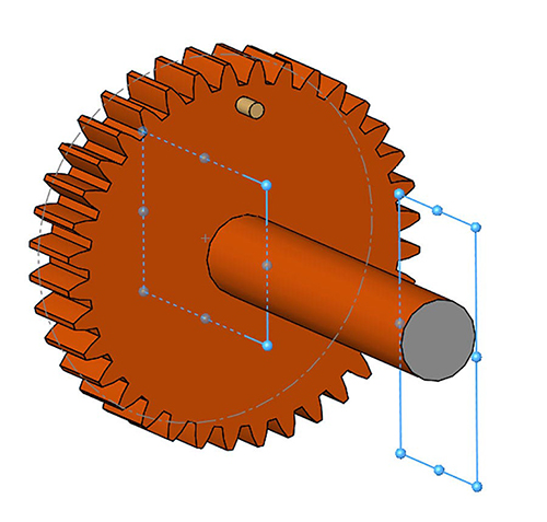
- 1 x solar gear (orange)
- 1 x ring gear (black)
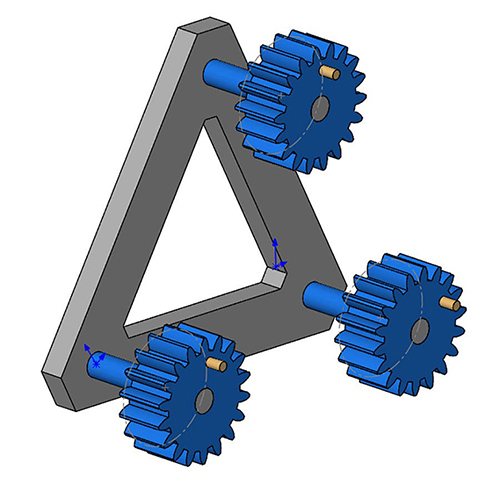
- 1 x provider
- 3 x provider shafts
- 1 x solar shaft
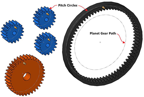
In every of the gear half information, pitch circles have been created as development circle sketches. The Ring gear has a further development circle drawn to information the trail of the Planet gears. This might be key to right movement and might be referred to as the Planet Gear Path.
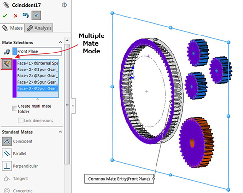
To begin assembling the gear system, we’ll mate the again face of every gear Coincident to the Entrance Aircraft of the meeting (make it possible for not one of the components are mounted in-place, if that’s the case right-click the half and choose Float). To hurry up this course of, use the A number of Mate Mode button, and choose the Entrance aircraft because the widespread reference.
Subsequent, mate the middle of the pitch circles on the Ring Gear and Solar Gear to the Meeting origin, they need to each be capable of spin.
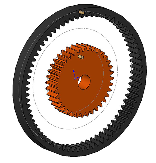
Subsequent, mate the middle of the pitch circles of the Planet Gears coincident to the Planet Gear Path sketch.
Now, mate the Provider shafts to the facilities of every Planet Gear (Concentric) and flush with their entrance faces (Coincident).
Get the Provider in place by including Concentric mates to every Provider Shaft, and one Coincident mate to deliver it flush with the again of one of many shafts.
Lastly, mate the Solar Shaft into place with one other set of concentric and coincident mates (this half is just not truly obligatory to point out the movement we’re after). We would like the Solar shaft to rotate with the Solar gear, so we may even mate Reference Planes along with the Coincident mate to hyperlink the rotation of the 2 components.
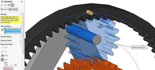
Now we’re prepared for the Gear mates. Choose the Pitch circles drawn on every gear to outline the Gear mates. This may outline the gear ratios, although cylindrical faces on the gears may be used and ratios could be manually overwritten. Add Gear mates between the three Planet gears and the Ring gear and one gear mate between a single Planet gear and the Solar gear (that is all that’s wanted for the whole gear movement). Whereas making the Gear mates, be sure you take a look at every and be sure that the spin instructions are right. Use the Reverse checkbox within the Mates Property Supervisor to repair if obligatory. Additionally, don’t worry about making the gear enamel mesh appropriately (we’ll repair this subsequent.)
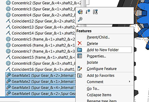
To group the gear mates right into a folder: shift-select the Gear mates, right-click, and choose Add to New Folder. Drag it to the highest of the Mates folder for ease of entry.
Subsequent, we’ll make one other group of mates to assist place the gear enamel appropriately, this may be executed by creating Parallel (or Angle) mates between reference planes on the gears and reference planes on the meeting. Relying on how the gears had been created, this could get the enamel to mesh appropriately, on this meeting the Prime planes are aligned with enamel and the Entrance planes aligned with gaps, so getting exact alignment is well attained with parallel mates. Utilizing mates for the alignment is preferable to dragging them into place as a result of they can be utilized sooner or later if realignment is important. Don’t neglect so as to add a further mate to align the Provider. Group these mates right into a folder as nicely. As soon as aligned, suppress the whole folder.
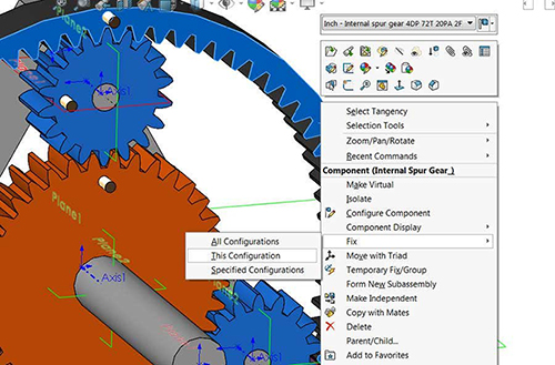
Now it’s time to create configurations for the three modes of motion. For every configuration a part might be mounted in place, earlier than fixing any part be sure you unsuppress the alignment mates to make sure these elements are within the right place after which suppress the alignment mates as soon as once more. Add a configuration referred to as “Ring Gear Fastened.” Proper-click the Ring Gear and choose Fastened, This Configuration solely.
To check movement, rotate the planetary gears by the Provider for finest outcomes.
For the second configuration, copy and paste the Default Configuration and rename it “Solar Gear Fastened.” Align the gears and repair the Solar Gear on this configuration solely.
Repeat the method, naming the third configuration “Provider Fastened” and repair the provider solely in that configuration.
If at any level after switching configurations the gear enamel don’t mesh appropriately, first suppress the gear mates after which unsuppress the alignment mates. After the gears are realigned, you possibly can as soon as once more suppress the alignment mates and unsuppress the gear mates. Keep in mind that the gear enamel don’t have to mesh appropriately for the movement of the planetary gear system to be noticed, although it is going to have an effect on analysis instruments similar to interference detection.
Try our web site to be taught extra and uncover different SOLIDWORKS options or contact us at Hawk Ridge Techniques at this time. Thanks for studying!
Sponsored content material by Hawk Ridge Techniques
